Derrick S Mu
Georgia Institute of Technology
Mechanical Eng. '22
ARM Lab
Undergraduate Researcher
•
ME 2110
Undergraduate TA
•
Invention Studio
Prototyping Instructor /
CNC Apprentice
New York, NY
•
Atlanta, GA

•
•
•
Listed below is some of the projects I have worked on over the years that vary from personal projects to competition projects.
I created a master-slave robot arm with my brother to compete in Science Olympiad. Both years had the robot arm accomplish different tasks but we had made a robot arm that was multi-use so all that needed to be changed between the two years were the effectors on the robot arm base and robot arm itself.
In 2016, the robot arm had to pick up ping pong balls, lego bricks, pencils, and dice and also flip the dice.
In 2017, the robot arm had to pick up stacks of pennies, flip them to face tails up, and place them in the center of a bullseye.
The robot arm went through many iterations to create proper gear ratios that would effectively overcome the moment arm the robot arm would be under.
The dimensions for the master and slave were proportional based on the slave's arm. The slave's dimensions were determined by finding out what length was needed to fully extend to all parts of the field to allow for the arm to manipulate the entire field.
I programmed the potentiometers on the master arm and servos on the slave arm with an Arduino.
I created an electric vehicle with my brother to compete in Science Olympiad. Both years required the robot to go as fast as possible across 8.5m and stop to the nearest centimeter at a random distance from 9m to 12m.
The design choice to use 3 wheels on the electric vehicle was to decrease the amount of error that could be caused. A triangle has only on point to pivot on while a rectangle has many points to pivot from and is harder to notice when misaligned.
The motor chosen was a Mamba Pro, due to its high velocity and torque.
Banebots wheels with a durometer of 30 Shore A because it gave the desired hardness to allow for the vehicle to travel quickly but also stop quickly.
To aim, the electric vehicle had a laser pointer that could measure distance mounted on it. The laser pointer would be pointed towards a wooden dowel placed on the target point.
An encoder was placed on the shaft to allow for accurate stopping.
In 2017, there was the added challenge of going through two soup cans placed to the right of the track.
To account for the change in the track, a servo was placed at the front of the vehicle that allowed it to curve and turn at different angles.
A gearbox was created to account for a Stepper Motor that allowed for even closer precision to the desired distance points. All the gears were plastic to reduce weight.
I created a mousetrap vehicle vehicle to compete in Science Olympiad. The event required for a vehicle to push a cup forward 4 meters and then go backwards to a random point to the closest centimeter.
To accomplish this, the entire chassis was CADded and 3D printed to allow for the lightest chassis possible without losing structural integrity. This would allow for the vehicle to move faster.
The wheels were also CADded and 3D printed and an O-ring was wrapped around them to allow the wheels to have more friction to stop and move faster.
To allow for consistant runs, a telescope was made to aim at a wooden dowel that was placed at the target point. The telescope was made using two magnifying lenses and wrapping two strands of hair over them to create a crosshair.
The vehicle would stop based on how much the wingnut was wound around the threaded rod in the back. The amounts of thread used on the rod and the size of the wheels were chosen to give a 1/16" accuracy.
A robot was created on a team of three to compete in a competition that was a part of our ME 2110 course. The competition consisted of placing a 2" wooden sphere on top of a dome, placing 0.5" diameter dowels on the side of the dome in a specified zone, and clearing 2" wooden cylinders away from a bullseye.
The video explain most of the design and manufacturing process.
I was mainly responsible for building the entire robot.
The entire robot was CADded and many of the mounts for the effectors were 3D printed.
For the arm that lifted the 2" wooden sphere, a 2:1 gear ratio was chosen to allow for there to be more torque when the arm placed the sphere. This would ensure our sphere was placed and quite possibly remove opposing team's spheres.
The panels that flapped to the side were powered by mousetrap springs that were placed on hinges. The mechanism that controlled when the flaps would open was a gate that was connected to the back of the robot with string. At a certain distance, the gate would pull off and release the flaps.
A caster wheel was placed in the front to allow for the robot to fully extend towards the dome and stop at a specified distance away from the dome. This was done to allow the robot to overcome discrepancies between different competition tracks.
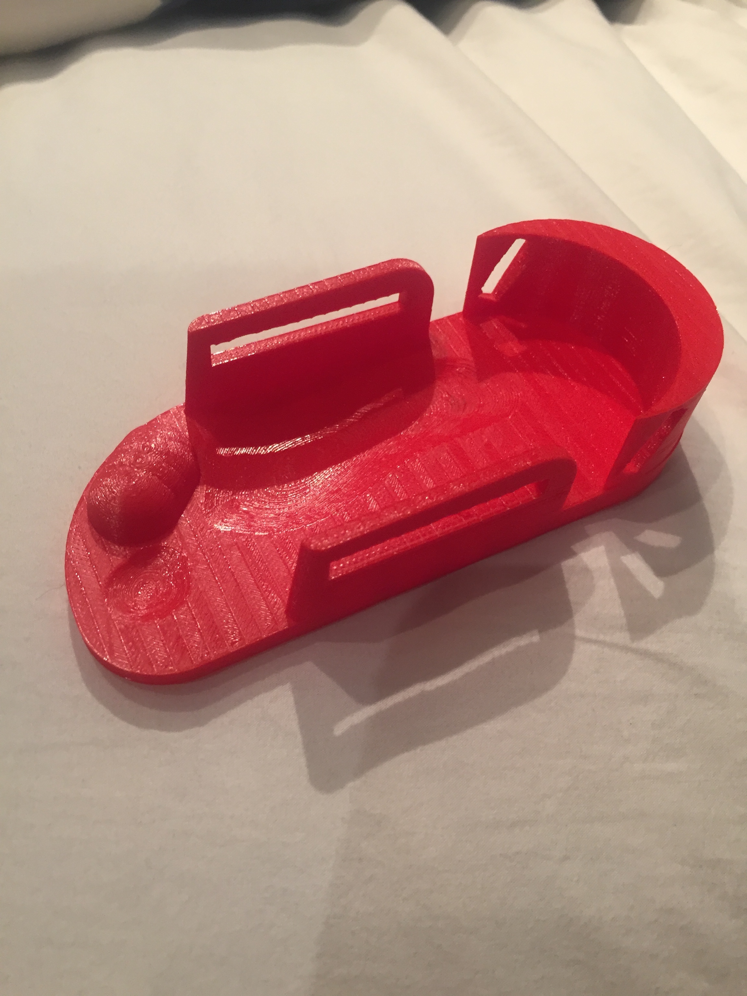
A foot brace was CADded and 3D printed to help assist a girl who was missing toes in ambulation and to avoid amputation.
First, a scan of the patient's foot was created by using a Structure 3D scanner. This allowed for our foot brace to have the exact footprint of the patient.
Then, several designs were created and tested to see which design provided the best support and comfort.
In the end, the design pictured below was chosen. The cylindrical extrusion at the front was created to help with the aesthetics and velcro was placed through the rectangular holes to be used as straps.